RP6502-PICO
RP6502 - Standalone Machine
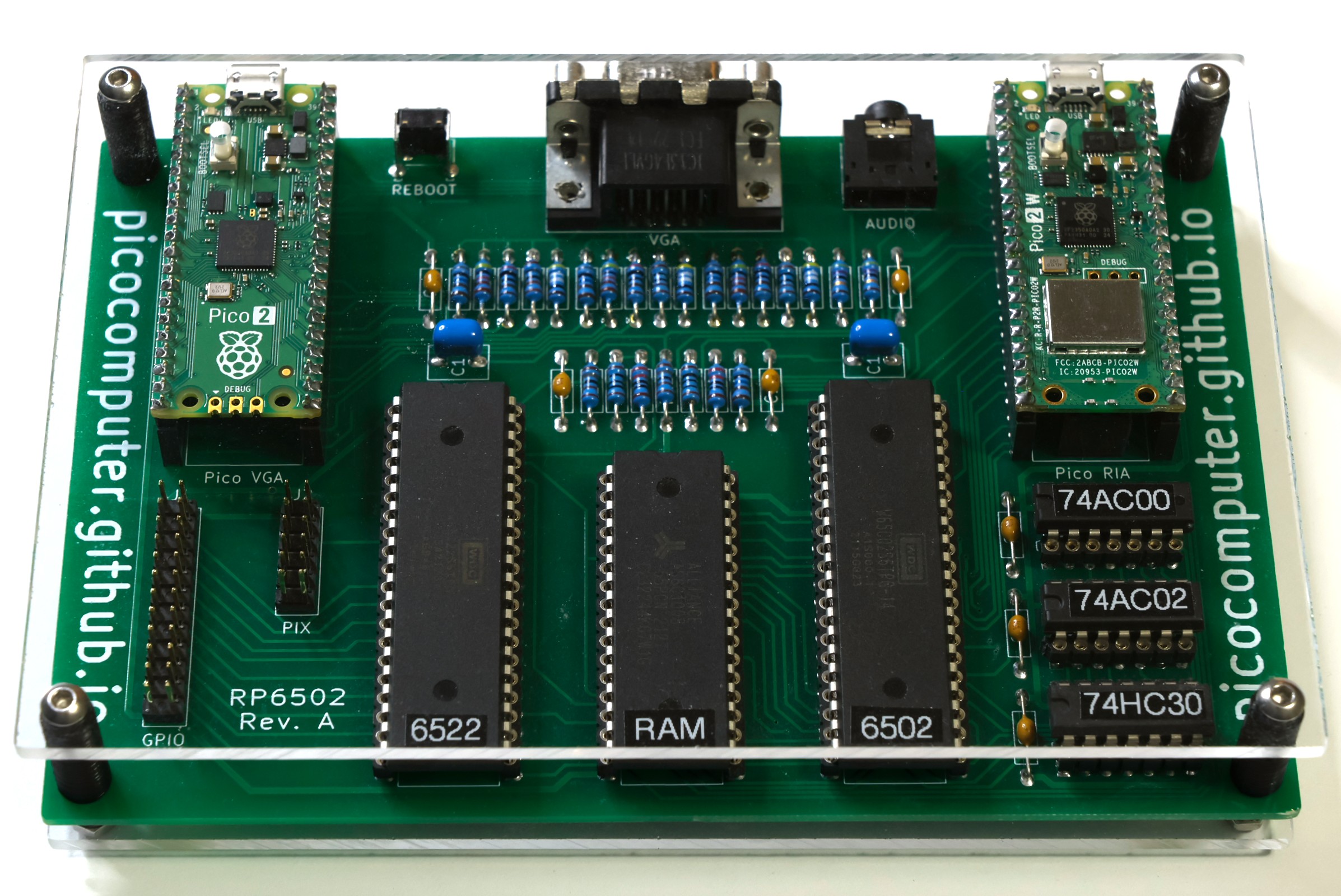
The RP6502-PICO is the standalone machine, a 6502 computer you build yourself. It is the original Picocomputer, and the project is named after the Raspberry Pi Pico it was first built on. The machine is one circuit board with a WDC 65C02, a WDC 65C22, a RAM chip, three logic chips, and two Raspberry Pi Pico 2 boards, which are the entire modern side of the machine. One Pico runs the RP6502 Interface Adapter (RIA) for USB, storage, and sound, and a Pico 2 W in that socket adds Wi-Fi and Bluetooth. The other Pico runs the video system, the RP6502 Video Graphics Array (VGA).
This page is the reference for the RP6502-PICO: its schematic and how to build one, firmware updates, the console and the monitor, storage, settings, the devices it drives over USB and Bluetooth, its network features, and the PIX bus between its two Picos.
Schematic and Building
RP6502-PICO (pdf)
Rev. A and Rev. B boards are identical except for the debug connectors under the RIA. They do nothing even when connected, so they were removed — mostly so folks would stop asking about them.
To solder, or not to solder — that is the question. You can homebrew a 6502 today without ever touching a soldering iron. Choose your path.
Firmware Updates
Download the pico zip and unpack the UF2 files inside it. The VGA file is the same for everyone. The RIA file depends on which Pi Pico you have. Use the “-w” if you have a Pi Pico 2 W.
To program a new Pi Pico, or one with a failed flash, hold its BOOTSEL button while plugging it into a computer, and copy the UF2 file to the storage device that appears. The computer can even be another RP6502-PICO, so one Picocomputer can build or repair the next. A failed flash cannot “brick” a Pi Pico, because this method always works.
On a working system, updates don’t need BOOTSEL. Put the UF2 files on a USB drive, plug it into the RIA, and flash both from the monitor. The system reboots after each one.
FLASH rp6502-<version>-ria-w.uf2
FLASH rp6502-<version>-vga.uf2
Console
The console of an RP6502-PICO is on the console manifold, and a terminal can be attached in three ways:
VGA and USB keyboard. In the standard configuration with a VGA module, the console is accessed with a VGA monitor, or an HDMI display with a VGA-to-HDMI cable, and a USB keyboard plugged into the RIA.
USB CDC ACM. Connect the USB port on the VGA module to a computer and access the console over the USB CDC ACM serial port that appears. No driver is needed.
Telnet. With a Pi Pico 2 W, the console is also on the network. See Telnet Console for setup.
5V Power is applied to the VGA module, enough for all your devices plus one watt for the RP6502-PICO itself.
Inside the machine, the console is a UART between the RIA and the VGA module: 115200 bps, 8-bit words, no parity, 1 stop bit.
The VGA terminal stops responding to the size query of the line editor if a telnet or USB terminal is connected. If both USB and telnet terminals are connected at the same time and both reply, the system may get confused. If pagination or word-wrap seem wrong, check what terminals are attached to the console manifold.
Monitor
A fresh RIA boots into the RP6502 monitor. It is not an operating-system shell; think of it more like a UEFI shell. Its main job is loading ROMs, with just enough hardware and locale configuration to get going — kept deliberately minimal.
The monitor runs on the console, so it is reachable from any terminal on the console manifold.
The monitor’s built-in help is extensive and always current. Type
HELP to get started, then dig into deep help like HELP SET PHI2.
The table lists every command.
Command |
Description |
|---|---|
|
Show the list of commands, the help of a command, or the
help text of an installed ROM. |
|
Show the credits, or a guide to the monitor. |
|
Show the state of the system and of every connected device. |
|
Show or change a setting. See Settings. |
|
List a directory. |
|
Show or change the current directory. |
|
Change the current drive. |
|
Make a directory. |
|
Delete a file or an empty directory. |
|
Copy a file to a new name or into a directory. |
|
Rename a file or a directory, or move it on the same drive. |
|
Show, label, format, erase, or verify a drive. See Storage and ROMs. |
|
Load a ROM file. The 6502 starts if the ROM has a reset vector. |
|
Show the help text of a ROM file. |
|
Install a ROM file in the flash of the RIA. |
|
Load and start an installed ROM. |
|
Remove an installed ROM. |
|
Start the 6502 at the current reset vector, $FFFC. |
|
Restart the RIA. See Reset and Reboot. |
|
Flash a UF2 file to the RIA or the VGA. See Firmware Updates. |
|
Write a file. Binary chunks follow. |
|
Write memory. Binary data follows. |
|
Read or write memory. XRAM is at $10000-$1FFFF. |
Use the LOAD command to load ROMs in .rp6502 format. A ROM
describes the state of the machine as it comes out of reset, and a
single ROM can hold every piece of code, video and audio a program
needs. Use INSTALL to put a ROM in flash; from there it can be run
directly, or SET BOOT will load it whenever the RIA boots. These
files are built with the SDK, where the ROM File Format is documented.
A few monitor commands, such as UPLOAD and BINARY, exist for
developer tools rather than for people. See the SDK for the tools
that use them.
Storage and ROMs
Files live on a USB flash drive. Any USB flash or floppy drive is read and
written as FAT. ExFAT is ready to go and will be enabled when the patents
expire. 1 MB of flash holds the ROMs you INSTALL, and
SET BOOT picks one to load at power-on. ROMs do not need to be installed,
they are intended to be loaded directly from mass storage devices.
USB drives are named MSC0: to MSC9:, or 0: to 9: for
short, and installed ROMs are on the null drive, :, where a ROM
installed as NAME is :NAME.
The DISK commands work on a whole drive. FORMAT and ERASE ask
you to type YES before they start.
Command |
Description |
|---|---|
|
Show the device, the format, and how full the drive is. |
|
Show or set the volume label. |
|
Create a filesystem. |
|
Overwrite every sector with zeros. |
|
Read every sector and report the bad ones. |
Reset and Reboot
While reset is low, the 6502 is stopped and the monitor is connected to
the console. Reset is mostly handled automatically, but the RP6502-PICO
also needs a way to stop a wedged 6502. Two monitor commands bring reset
high. Either LOAD a ROM that has a reset vector, or use the RESET
command if you’ve prepared RAM some other way. To drop reset from high to
low and return to the monitor, even from a wedged 6502, use any terminal on
the console manifold:
Press Ctrl-Alt-Del from a USB keyboard.
Send a break from a serial terminal.
Send a break from a telnet terminal.
The reboot button is wired to the RIA RUN pin. Rebooting restarts the RIA and
loads any configured boot ROM, just like at power-on. REBOOT does the
same. Never wire a button to RESB; the RIA must stay in control of it.
Settings
SET with no arguments shows every setting, and HELP SET followed by
a setting gives its details. The RIA keeps the settings in its flash, so
they last through a reboot. A Pi Pico 2 W adds BLE and the settings of
Wi-Fi Setup and Telnet Console.
Command |
Description |
|---|---|
|
The 6502 clock, from 100 to 8000 kHz. A speed that is not available rounds up to the next one that is. |
|
The installed ROM that loads and starts at power-on and at reboot.
|
|
The time zone. See Network Time Protocol (NTP). |
|
The locale, |
|
One or more keyboard layouts, such as |
|
The code page. 0, the default, follows |
|
The display type: 0 for 640x480 on 4:3 displays, 1 for 16:9 displays, with 1280x720 for the 16:9 canvases and 640x480 for the others, or 2 for 1280x1024 on 5:4 SXGA displays. Every canvas works on every display type. Video Timing gives the timing of each. |
|
The NFC reader. See Near Field Communications (NFC). |
|
Bluetooth LE. See Bluetooth. |
USB
The RIA is a USB host, with one USB port. Plug a hub into it to connect more than one device. The RIA drives keyboards, mice, gamepads, hubs, UART serial adapters, MIDI instruments, NFC readers, and floppy and flash drives. The firmware includes gamepad drivers for Generic HID, XInput, and PlayStation controllers.
Bluetooth
With a Pi Pico 2 W as the RIA, the RP6502-PICO supports Bluetooth LE (BLE) keyboards, mice, and gamepads. The other machines use the Bluetooth of their host. Bluetooth Classic (BR/EDR) is not supported. BLE has been everywhere since Bluetooth 4.0 (June 2010), so compatible devices are easy to find, though the occasional oddball still turns up.
To add a device, run the monitor command SET BLE 2 to enter pairing
mode; the LED on the Pico 2 W blinks while it’s pairing. Put your
device into its own pairing mode too. Check its manual, but it’s
probably a button and some more blinking. When the blinking stops, the
device is connected and bonded, so it reconnects automatically from then
on.
Wi-Fi Setup
A Pi Pico 2 W as the RIA adds Wi-Fi 4 (802.11n), for the telnet console, modem emulation, and NTP. Networking is only on the RP6502-PICO today, and support for other machines is planned.
The radio is configured from the monitor. Set the network name and the
password, and the radio connects. The STATUS command reports the state
of the connection.
Command |
Description |
|---|---|
|
Turn all radios on (1, the default) or off (0) without disturbing any other setting. |
|
The two-letter code for the country the radio operates in, such as
|
|
The SSID is the Service Set Identifier, which is the name of the
network the radio joins. Run |
|
The password for the network. Use |
Network Time Protocol (NTP)
The real-time clock synchronizes with internet time servers whenever
Wi-Fi is connected. The STATUS command reports what NTP is doing.
The clock keeps UTC. Set your time zone with SET TZ for local time,
and run HELP SET TZ for guidance. Daylight Saving is applied
automatically where the locale observes it.
Telnet Console
The console can be exposed over the network. A telnet client is then a console like any other, for the monitor and for a running 6502. The traffic is unencrypted, so anything typed or printed can be read along the way, including the key.
Command |
Description |
|---|---|
|
The TCP port to listen on. The default is |
|
The passkey a client sends to connect. Use |
The telnet console starts listening once KEY is set and PORT is
non-zero.
Modem Emulation
The RP6502-PICO emulates a Hayes modem — the classic AT command set — for reaching BBSes (bulletin board systems). It places outgoing calls and answers incoming ones over either raw TCP or telnet. As with the telnet console, the connection is unencrypted.
Example AT commands:
ATA— Answer incoming callATDexample.com:23— Dial a BBS by addressATDS=0— Dial phonebook entry (0-3)+++— Escape back to command modeATE1— Set echoATH— Hang upATO— Return to callATQ0— Set quietingATSxxx?— Query register number xxxATSxxx=yyy— Set register number xxx with value yyyATV1— Set verbosityATX0— Set progress messagingATZ— Load profile from flashAT&F— Load factory profileAT&V— View profile, stored profile, phonebook, and networkAT&W— Write profile to flashAT&Z0=example.com:23— Save phonebook entry (0-3) to flashAT\L=23andAT\L?— Listen port forATA(0 disables)AT\N0orAT\N1andAT\N?— Network mode: 0=raw TCP, 1=telnetAT\T=ANSIandAT\T?— Terminal type advertised during telnet negotiationAT+RFCC=US,AT+RFCC?, andAT+RFCC!— Access RIA setting RFCCAT+SSID=your_ssid,AT+SSID?, andAT+SSID!— Access RIA setting SSIDAT+PASS=your_passandAT+PASS?— Access RIA setting PASS
Each AT+ setting uses = to set, ? to query the current value,
and ! to list (AT+SSID! scans for nearby networks, AT+RFCC!
lists supported country codes). Lists word-wrap to 80 columns.
The modem is available as a set of special device names:
AT:is transient. It starts from factory defaults, has no phonebook, andAT&Whas nothing to save.AT0:throughAT9:are ten independent profiles, each with its own flash-backed settings and four-slot phonebook (AT&Z0-AT&Z3).
When you open a numbered device, it loads its saved profile. AT&W
writes the profile back, ATZ reloads it, and AT&F restores
factory defaults. Up to four modem devices can be open and in use at
once.
The AT+ commands (+RFCC, +SSID, +PASS) pass straight
through to the global RIA settings and take effect immediately, no matter
which modem device is open.
Virtual COM Port
If you need serial ports beyond the console UART, USB adapters are available for CMOS/TTL, RS-232, RS-422, and RS-485, and each one appears as a Virtual COM Port (VCP). RP6502-PICO firmware includes drivers for FTDI, CP210X, CH34X, PL2303, and CDC ACM.
The STATUS command lists any connected VCP devices. Open one like a
file, using a special name. By default "VCP0:" opens at 115200 bps
with 8 data bits, no parity, and 1 stop bit. Set the baud rate with
"VCP0:115200", or the full bit configuration with
"VCP0:115200,8N1". The file won’t open if your hardware can’t
support the requested configuration.
open("VCP0:1200,7E2", O_RDWR);
// then read and write
Generous FIFO buffers serve both directions, and both reads and writes are non-blocking. Reads can return 0 bytes, and writes may send less than you asked for — resubmit any remaining bytes on a later call.
MIDI
MIDI instruments attached to the machine appear as devices, and the
STATUS command lists them. RP6502-PICO firmware includes a USB MIDI
host driver, so a USB instrument plugs right in. Each virtual cable is
its own device — "MIDI0:" onward, assigned in the order cables
appear, up to four at a time. A simple keyboard is one cable (1X1); a
multi-port interface is several. Open one like a file.
A cable opens in one of two modes, chosen by the open name. Bare
"MIDI0:" is raw — reads and writes are plain wire MIDI, the same
bytes a 5-pin DIN cable carries, with no timing and nothing added or
removed. Give a division instead, "MIDI0:480", and the cable is
timed: the RIA handles timing for you using the event format from
Standard MIDI Files, prefixing every message with a variable length
quantity delta time measured in ticks. The rest of this section is the
timed format.
In timed mode, time starts at the open. The first byte in either direction is a delta measuring from the open itself, and a delta of zero means right now. Writes are scheduled — the RIA holds each message and sends it to the instrument exactly on time, so your program only needs to keep the buffer fed. Reads are a recording — incoming messages arrive with delta times measuring when they actually happened, ready to store in a file or play back later.
The division is ticks per quarter note, the value an SMF carries in its header. It accepts 1 to 32767 and is fixed while open; reopen between songs to change it. A cable can be input, output, or both; reading an output-only cable or writing an input-only one returns an error.
Tempo changes on the fly with the standard SMF Set Tempo meta event,
which the RIA consumes locally and never forwards to the instrument. The
event is FF, a type, a length, then that many data bytes:
Control event |
Effect |
|---|---|
|
Set tempo in microseconds per quarter note — the standard SMF event. The tick rate becomes tempo × 1000 ÷ division. |
|
A wire System Reset. The doubled escape is the whole event, with no length byte. Unlike the others, it is sent to the instrument. |
Tempo defaults to 500000 µs per quarter note — 120 BPM, a 1041667 ns
tick at 480 PPQN. Every other FF event, including the rest of the
SMF meta set, is swallowed without effect, so a Standard MIDI File track
plays through nearly verbatim — division from the file header, tempo
events straight from the track:
open("MIDI0:96", O_RDWR); // division from the MThd header
// FF 51 03 07 A1 20  tempo = 500000 (120 BPM at 96 PPQN)
// then delta-timed events; the RIA paces them and tracks tempo changes
The RIA echoes every tempo event onto the read stream at the moment it
takes effect, so a recording is self-describing. A rejected event is
malformed, or carries a value of zero or out of range. The RIA echoes it
with its value zeroed and the tempo unchanged; zero is never a valid tempo,
so it unambiguously marks an event that didn’t apply. Your read parser must
handle FF: a second FF is a System Reset, and anything else is
a meta type and length to skip.
The stream carries raw wire MIDI messages after each delta time: channel
voice messages (running status accepted on writes), system common, and
single-byte real-time messages F8-FE. System Reset travels as the
FF FF escape in both directions: write a delta then FF FF to
send one, and a reset from the instrument is recorded the same way. The
undefined bytes F4 and F5 are quietly dropped.
System Exclusive, or sysex, is how instruments move the big stuff, like
patch banks and sample dumps, in one long message: F0, any number of
data bytes, then F7 to finish. Only the opening F0 takes a delta
time; the data bytes flow without timing until the F7, on writes and
recordings alike. Real MIDI lets real-time messages like clock barge
into the middle of a sysex — the RIA passes them through in place, so
expect the occasional F8-FE byte inside a recorded dump. And if a tempo
echo comes due during a dump, the recording closes the sysex early and
reopens it after — everything arrives, just split into two
F0 … F7 fragments.
Delta times measure from the previous event, so timing stays exact over any song length. Events are anchored to an absolute tick count, and ticks are kept internally in nanoseconds, holding arithmetic rounding below one part per million. The error left over comes from the machine’s clock and transport. Where the RIA is paced by a crystal-driven microsecond timer and delivers over USB full speed, the crystal drifts single-digit milliseconds over a several-minute song and framing sets the moment-to-moment jitter near one millisecond — the same pace as the classic MIDI wire itself.
If your program stops feeding the buffer and resumes, messages already past due play immediately and the timeline continues from there. If you stop reading, the recording drops whole messages rather than backing up, and the timing of everything that survives stays exact. Reads and writes are non-blocking with the same short read/write rules as other non-blocking devices.
Closing a timed output cable blocks until its buffered tail has played
out on schedule. The final notes reach the instrument before close returns,
along with the note-offs that end them, and nothing is left ringing.
sync does the same without closing. It waits for the schedule to catch
up between songs. Both follow the timeline, so a far-future delta
still in the buffer makes them wait that long. If a sysex is still open
when a timed cable closes, the RIA sends its F7 so the instrument is
not left waiting mid-dump. A raw cable has no schedule, so close and
sync flush what is buffered, and they inject no F7.
Near Field Communications (NFC)
NFC cards have become a popular media replacement in the retro community, and they map neatly onto the RP6502’s use of “ROM files” in place of “ROM cartridges”. In 1983 you might have grabbed a cartridge with colorful stickers to home in on the exact dopamine hit you were after. NFC cards are cheap and just as easy to decorate, whether with stickers or direct printing. Grab a card, tap it on the reader, and the ROM you want loads instantly.
You’ll need a PN532 card reader with a USB interface. It’s the only reader RIA firmware drives, and it’s cheap — around $10 USD. You’ll also want a card (or fob, or sticker) for each ROM you plan to support. New to NFC? Buy a pack of NTAG215 cards and a sharpie.
Do not buy a kit of separate USB-to-UART and PN532 boards unless you want an unsupported project on your hands. Buy a single board with everything already engineered and ready to use.
With the reader plugged in, run the monitor command SET NFC 2 to
start USB detection. It may probe your other VCP devices with PN532 data
along the way; that’s normal. You’ll hear an error buzz, or two beeps for
success. You can also run STATUS to see whether (NFC) is listed
next to one of your VCP devices.
SET NFC 1 turns the reader on and SET NFC 0 turns it off; the
choice persists across reboots (a successful SET NFC 2 also leaves it
on). SET NFC 86 forgets the paired reader so a later SET NFC 2 can
pair a different one.
From now on, scanning a card produces one of three sounds: an error buzz if something went wrong, two beeps for success, or a single beep for a partial success.
Program each card with the filename and arguments of the ROM to launch.
If you’d load the ROM with LOAD /jigsaw.rp6502, put an NDEF TEXT
record on the card holding just /jigsaw.rp6502 — no load command. A
leading / is implied if you leave it off, and the current working
directory is ignored.
Paths with spaces need quotes, and you can include arguments:
"/My Games/jigsaw.rp6502" cat.bmp
When a card is read, every mounted drive is scanned for the ROM file. On a match, you get two beeps, the 6502 stops, the current drive and directory switch to the ROM’s location, and the new ROM starts loading. If that ROM is already running, you get a single beep and nothing else happens.
To search just one drive, name it in the text record:
MSC0:/encabulator.rp6502
A card may also name an installed ROM, :NAME. That ROM launches the
same way, with the same beeps, except that no drive is scanned and the
current drive and directory stay where they are. A name that is not
installed gives the error buzz.
NFC Device API
Applications can take over the NFC reader for advanced uses, or to help
program NFC tags. While the "NFC:" device is open, automatic ROM
launching is suppressed.
int fd = open("NFC:", O_RDWR);
The PN532 reader runs autonomously on the RIA. The 6502 arms operations
with write() and polls results with read(): NFC_CMD_READ
returns the current tag data immediately, NFC_CMD_WRITE arms a write,
and NFC_CMD_CANCEL disarms a pending one. State changes and write
completions are posted to read() automatically.
write() – Commands
write() is non-blocking and streaming. A call may consume less than
you passed; resubmit the remaining bytes on a later call.
Byte |
Command |
|---|---|
|
Arm a write |
|
Disarm pending write |
|
Return current tag data |
|
Play success tone 1 |
|
Play success tone 2 |
|
Play error tone |
The NFC_CMD_WRITE payload starts with the start page, a two-byte
length, then the tag data. page is the NTAG page to begin writing at
(page 4 is the start of user data). Data is written in 4-byte pages, and
the final page is zero-padded if the payload isn’t a multiple of 4. The
write arms once the full payload arrives and runs on the current card or
the next one presented. A second NFC_CMD_WRITE overwrites the first.
The payload may be at most 888 bytes; a longer length is rejected with the error tone and never armed. A write also fails (error tone) if it would run past the card’s NDEF data area or target a page below 4, and a zero-length payload completes immediately as a no-op.
NFC_CMD_READ always returns NFC_RESP_READ on the next read();
if no card data is available, the length is zero.
read() – Responses
read() is non-blocking and streaming. It returns 0 bytes when there’s
nothing new. Responses may be split across multiple calls, so callers
must buffer and reassemble them. State changes are sent once per change,
including once right after open(). Only the latest state is tracked, so
a rapid transition (such as NFC_RESP_CARD_INSERTED immediately followed
by NFC_RESP_CARD_READY) may be coalesced to the later state if you don’t
read() in between.
Byte |
Meaning |
|---|---|
|
Read result |
|
Armed write complete |
|
State: no reader attached |
|
State: no card present |
|
State: card present, tag data not ready |
|
State: card present, tag data ready |
The NFC_RESP_READ payload is a two-byte length followed by raw tag
data starting at page 0, and it may span multiple read() calls.
In the page layout, pages 0-2 are UID/lock bytes, page 3 is the Capability
Container (CC[2] * 8 = max NDEF bytes), and pages 4+ are user data
(TLV-wrapped NDEF records terminated with 0xFE).
After NFC_RESP_READ or NFC_RESP_WRITE, send one or more tone
commands or play your own sounds. Typically you request reads on
NFC_RESP_CARD_READY and arm writes on NFC_RESP_NO_CARD, but you
can also arm a write after reading and verifying a card. The cached
tag image is not refreshed by a write, so re-present the card before the
next NFC_CMD_READ if you want to read back what you wrote.
PIX Physical Layer
None of this is needed to program the machine. What follows is the bus itself, for anyone building a device to put on it.
On the RP6502-PICO, PIX is a physical bus between the RIA and the VGA module. High-bandwidth devices like video systems need a bus of their own. PIX is that bus: an addressable broadcast system that any number of devices can receive, narrow enough to fit the GPIO budget of a Raspberry Pi Pico, wide enough to move data as fast as the 6502 writes.
The signals are PHI2 and PIX0-3. This is a double-data-rate bus. It shifts PIX0-3 left on both transitions of PHI2, so a 32-bit frame is sent in just 4 PHI2 cycles. A PIO block on a Raspberry Pi Pico decodes it, since PIO is essentially a shift register.
Bit 28 (0x10000000) is the framing bit, set in every message. When the bus is idle, an all-zero payload repeats on device ID 7. A receiver synchronizes by checking that PIX0 is high on a falling transition of PHI2; if it isn’t, stall until the next clock cycle.
Bits 31-29 (0xE0000000) hold the device ID of a message:
Device 0 — XRAM broadcasts only. The extended registers of device 0 are handled inside the RIA and are never sent on the bus.
Device 1 — the VGA.
Devices 2-6 — open for user expansion.
Device 7 — synchronization. (0xF0000000 is hard to miss on test equipment.)
For devices 1-6, the remaining bits address an extended register:
Bits 27-24 (0x0F000000) — the channel ID; each device can have 16 channels.
Bits 23-16 (0x00FF0000) — the index of the register within that channel.
Bits 15-0 (0x0000FFFF) — the value to store in the register.
The RIA broadcasts every change to XRAM as a device 0 message, with the XRAM address in bits 15-0 and the XRAM data in bits 23-16. Each device keeps a local replica of the XRAM it uses, typically all 64 KB.
Backchannel
The RP6502-PICO hardware is constrained by GPIO pins, which is why it uses two Raspberry Pi Pico 2 boards. The backchannel is a hack to recover a single pin. The 6502 programmer never has to think about any of this.
Because the PIX bus is unidirectional, the VGA system can’t send data straight back to the RIA. The UART Rx path won’t do either — it would add framing overhead or unusable control characters. But the PIX bus has plenty of idle bandwidth (it only carries data when the 6502 writes to XRAM), so all Tx data is routed over PIX, leaving the UART Tx pin free to reverse directions and serve as the backchannel.
Values 0x00 to 0x7F send a version string as ASCII, terminated by 0x0D or 0x0A. Sent immediately after the backchannel-enable message arrives for it to appear in the boot message.
When bit 0x80 is set, the 0x70 bits give the command type and the 0x0F bits give a scalar for that command.
0x80 VSYNC - The scalar will increment and be used for the LSB of the RIA VSYNC register.
0x90 OP_ACK - Some XREG locations are triggers for remote calls which may fail or take time to complete. This acknowledges a successful completion.
0xA0 OP_NAK - This acknowledges a failure.
Because waiting for an entire character to decode over UART is lost time for VSYNC, a predictive algorithm suspends ACK/NAK around the expected window for a VSYNC so it can be edge triggered on the first bit.